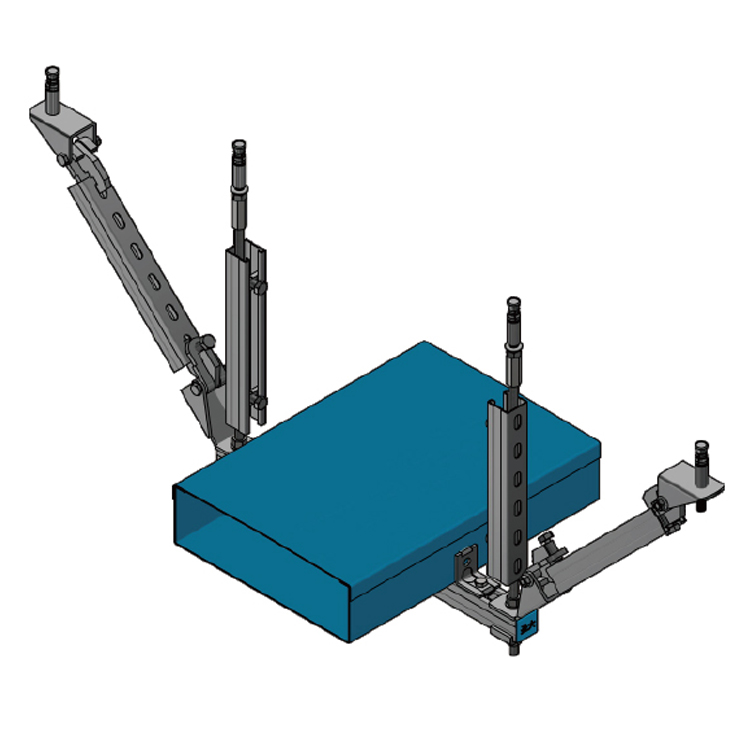
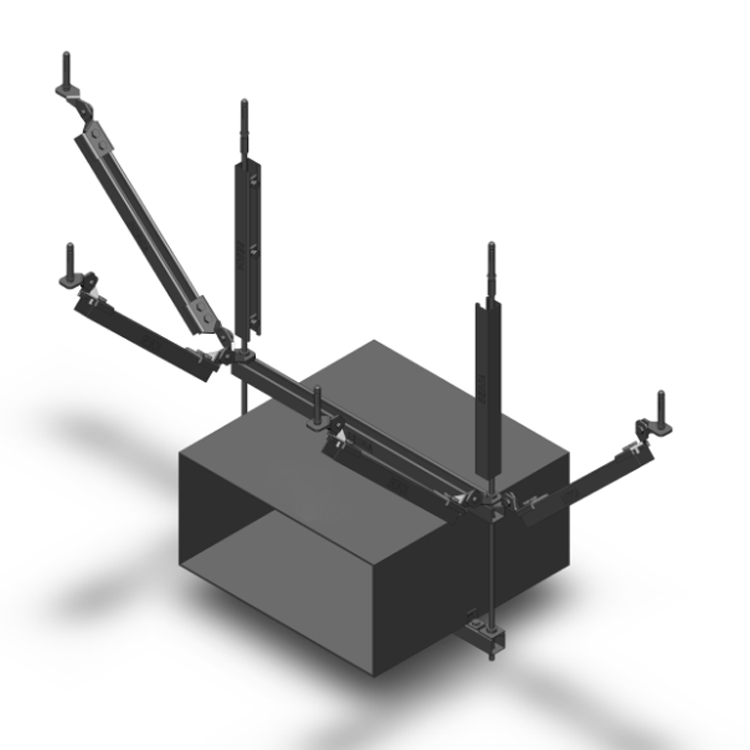
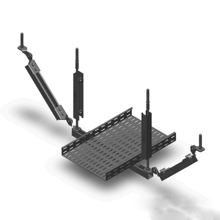
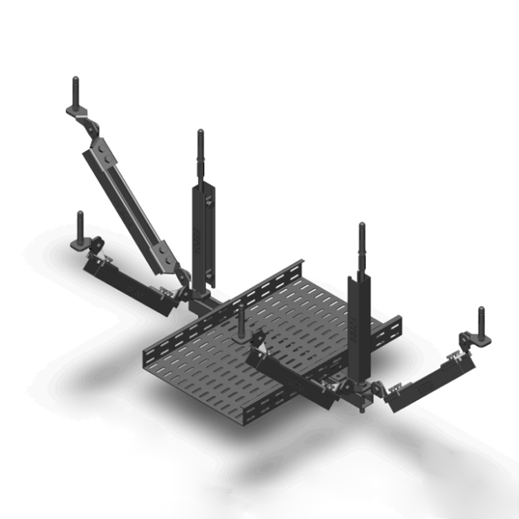
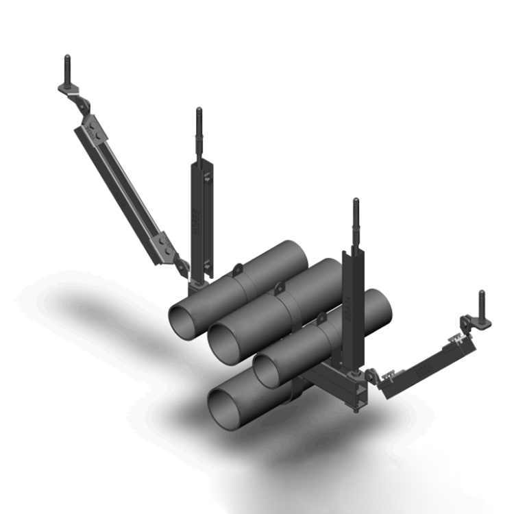
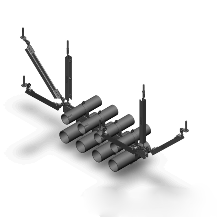
Lateral seismic support bracket for air duct
 | |||||||||||||||||||||||||||||||||||||||||||||||||||||||||||||||||||||||||||||||||||||||||||||||||||||||
Product Name: Lateral Seismic Support for Air Ducts 1. Material guarantee: High quality carbon structural steel is used; 2. Surface treatment: hot-dip galvanized 65um 3. Test certification: IS09000-2008 factory certification, national seismic support testing certification 4. Comprehensive drawing design 5. Industrial customized products, simple and easy-to-use concept, ensuring safety
Design Description of Seismic Support System
1、 Design Basis:
1. The current main national norms, regulations, and relevant industry standards:
1.1 GB50981-2014- "Code for Seismic Design of Building Mechanical and Electrical Engineering" 1.2 CJ/T476-2015- General Technical Conditions for Seismic Supports and Hangers of Building Mechanical and Electrical Equipment 1.3 CECS420:2015- Code for Installation and Acceptance of Seismic Supports and Hangers 1.4. GB50011-2010- Code for Seismic Design of Buildings 1.5. GB50243-2002- Code for Acceptance of Construction Quality of Ventilation and Air Conditioning Engineering 1.6. GB50017-2003- Code for Design of Steel Structures 1.7. 03K132-2003- "Duct Support and Hanger" 1.8. 03S402-2003- "Indoor Pipe Supports and Hangers" 1.9. 04D701-3-2004- Cable Tray Installation 1.10, 03SR417-2-2003- "Installation Drawing for Prefabricated Pipe Hanging Support" 1.11, 95R417-1-2002- Installation Drawing for Prefabricated Pipe Hanging Support 1.12. GB/T3098.1-2000- Installation Drawing for Prefabricated Pipe Hanging Support 1.13. GB50235-1997- Code for Construction and Acceptance of Industrial Metallic Piping Engineering 1.14. GB/T17116.1-1997- "Pipeline Supports and Hangers Part 1: Technical Specifications" 1.15, GB/T18684-2002- Technical Conditions for Zinc Coating 1.16. GB/T700-2006- Carbon Structural Steel 1.17 JG160-2004- "Expansion type and expansion hole type building anchor bolts for concrete" 1.18, GB/T13912-2002- "Technical Requirements and Test Methods for Hot Dip Galvanized Coatings on Steel Parts with Metal Coating" 1.19, GB/T9799-2011- Zinc Electroplated Coatings on Steel with Metallic and Other Inorganic Coatings after Treatment 1.20, GB/T9799-2011- Zinc Electroplated Coatings on Steel with Metallic and Other Inorganic Coatings after Treatment 1.21. ASCE.7-10- American Building Load Code
2、 Design pipeline scope
Buildings and mechanical and electrical engineering in areas with seismic fortification intensity of 6 degrees or above must undergo seismic design.
1. Water supply and drainage: (1) Indoor water supply, hot water, and fire protection pipelines with a diameter greater than or equal to DN65; (2) The pipelines inside the pump room. 2. HVAC: (1) Pipelines in boiler rooms, refrigeration rooms, and heat exchange stations; (2) A duct system with a rectangular cross-sectional area greater than or equal to 0.38 square meters and a circular diameter greater than or equal to 0.70 meters; (3) Smoke exhaust ducts, accident ventilation ducts, and related equipment. 3. Gas: Gas pipelines with an internal diameter greater than or equal to 25mm. 4. Electrical: (1) Electrical piping with an internal diameter of not less than 60mm; (2) Cable ladders, cable trays, and bus ducts with a gravity of not less than 150N/m. 5. Equipment: Equipment with a gravity greater than 1.8kN in suspended pipelines. 6. Other: Important mechanical and electrical engineering computer rooms, such as heat exchange stations, distribution substations, diesel generator rooms, communication rooms, fire control rooms, security monitoring rooms, etc.
Note: All components that make up seismic supports and hangers should be finished components, and the construction of connecting fasteners should be easy to install.
3、 Design requirements:
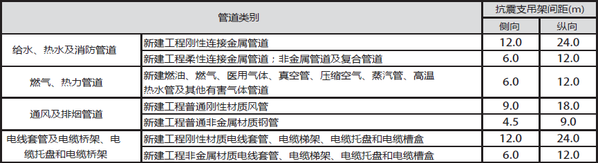
1. According to Article 8.1.2 of GB50981-2014 "Code for Seismic Design of Building Mechanical and Electrical Engineering", all components that make up seismic supports and hangers should use finished support components, and the structure of connecting fasteners should be easy to install; 2. According to Article 5.1.4 of GB20981-2014 "Code for Seismic Design of Building Mechanical and Electrical Engineering" and Article 5.1.4 of the article description, the support and hanger of smoke exhaust ducts, accident ventilation ducts and their equipment shall strictly adopt support and hanger with seismic function, and shall be purchased and installed according to technical requirements; 3. The initial spacing between seismic supports and hangers should meet the requirements of Article 8.2.3 of GB50981-2014 "Code for Seismic Design of Building Mechanical and Electrical Engineering" and comply with the provisions of Table 8.2.3: 4. The arrangement of seismic supports should be strictly in accordance with the requirements of Chapter 8.3 of GB50981-2014 "Code for Seismic Design of Building Mechanical and Electrical Engineering"; 5. The comprehensive coefficient of horizontal seismic force for pipelines shall be calculated in accordance with the requirements of Article 8.2.4 of GB50981-2014 "Code for Seismic Design of Building Mechanical and Electrical Engineering", and shall refer to the parameters in Article 3.4.5 and Table 3.4.1. When the calculation result is less than 0.5, take 0.5, and if it exceeds 0.5, calculate the actual value; 6. The mechanical verification of seismic support should include: verification of the connection between the support and the building structure (including anchor bolts and connectors); Force verification of members (including tension and compression verification); Stress verification of seismic connectors for brackets, etc; 7. The slenderness ratio of seismic support suspender and slant support shall meet Article 8.3.8 of GB50981-2014 Code for Seismic Design of Building Mechanical and Electrical Engineering: when the slenderness ratio of seismic hanger suspender is greater than 200, strengthening measures shall be taken.
4、 Technical requirements for seismic support product system:
1. C-type channel steel is a cold pressed formed channel steel with cross-sectional dimensions of 41mm * 21mm, 41mm * 41mm, 41mm * 52mm, 41mm * 72mm, etc. It is a standard profile with a length of 3000mm or 6000mm. The steel material is Q235B or above and meets the requirements of "Carbon Structural Steel" GB/T700-2006. The wall thickness is not less than 2.0mm. The back of the groove steel has strip-shaped installation holes and auxiliary gauge marks for easy installation and processing on site during construction, and for convenient pipeline installation, maintenance, and expansion in the future; 2. The inner edge of the seismic support C-shaped channel steel must have teeth with a depth of not less than 0.9 millimeters, and the installation of all accessories must rely on mechanical interlocking. It is strictly prohibited to use any installation method that relies on the friction of accessories to bear the force. Spring nuts that do not match the channel steel are not allowed to be used for all connecting accessories to ensure the reliable connection of the entire system. 3. The seismic support C-shaped channel steel is designed with axial reinforcement ribs to enhance the section stiffness and ensure that the channel steel section is not deformed during transportation, cutting, and installation; 4. The material of seismic connection components and tube bundles shall be Q235 or above, and shall meet the requirements of GB/T700-2006 Carbon Structural Steel, with a wall thickness of not less than 4mm; 5. The bundle and pad should come with screws and have anti loosening function, which is convenient for quick installation on the construction site, saves time and materials, and does not require cutting and installing screws on site; 6. Seismic supports are required to undergo a standard temperature rise curve test of 120 minutes in accordance with GB/T9978.1-2008 "Fire resistance test methods for building components", and obtain a fire test report from a national authoritative testing center; 7. The anti-seismic support is composed of anti-seismic anchor bolts, screw anti-seismic parts, anti-seismic connecting members and anti-seismic slant support. Assembly installation is adopted on site, and anti-corrosion treatment is carried out on the surface according to the on-site usage environment to avoid dust or paint aging and peeling during use, ensuring cleanliness and facilitating later maintenance; 8. Surface anti-corrosion treatment: 8.1. The seismic connecting components shall be treated with hot-dip galvanizing or passivated galvanizing, and shall comply with the national standard "Technical Requirements and Test Methods for Hot Dip Galvanized Coatings on Steel Parts with Metal Coatings" GB/T13912-2002 or "Zinc Plated Coatings on Steel with Metal and Other Inorganic Coatings" GB/T9799-2011 galvanizing regulations, and shall have relevant material, zinc layer, and salt spray test reports; 8.2. The surface of all single spliced and double spliced finished channel steels shall comply with the national standard "Technical Requirements and Test Methods for Hot Dip Galvanized Coatings on Steel Articles with Metal Coating" B/T13912-2002 or "Zinc Electroplating Coatings on Steel with Metal and Other Inorganic Coating" GB/T9799-2011 galvanizing regulations, and shall have relevant material, zinc layer, and salt spray test reports; 9. The expansion anchor bolts used must comply with the national standard "Expansion type and expansion hole type building anchor bolts for concrete" JG160-2004, and provide a testing report from the National Building Center; 10. The seismic support system used should have: 10.1 Test report for anchor bolts: ---ETA Joint Opening Concrete OPTION1 Report ---Tensile performance test report under non cracking concrete ---Test report on shear performance under non cracking concrete ---Tensile performance test report under cracked concrete ---Test report on fatigue load resistance performance ---Fire resistance bearing capacity performance testing report ---Corrosion resistance performance testing report
·Seismic Performance Crack Series Test Report for Cracked Concrete ---Repeated crack opening and closing performance test report ---Low cycle repeated tensile load performance test report ---Low cycle repeated shear load performance test report
10.2 Test report of anti-seismic connecting members, upright poles, connectors and slant support: ---National level mechanical performance testing report, ---Report on 2 million repeated fatigue tests of seismic main load-bearing connectors, ---Test Report on Bending Performance of Channel Steel ---Test report on compressive performance of channel steel ---Tensile Performance Test Report for Channel Steel ---Test report on mechanical properties of tube bundle ---Mechanical performance test report for connecting accessories ---Wear and corrosion resistance salt spray test report for related products 10.3 Test report for restraint: ---Test report on mechanical properties of tube bundle ---Control Fire Test Report 10.4 Report on Connecting the Lock Buckle: ---Test report on tensile performance of rolled edge of channel steel locking buckle ---Test report on anti slip performance of channel steel locking buckle rolled edge ---Report on 2 million fatigue load resistance test of channel steel lock buckle 10.5. Test report for the overall seismic support: ---Overall vibration performance test report (simulation experiment shall not be lower than 8 degrees (0.30g) under rare earthquake conditions) ---Overall fire performance test report to ensure the safety of seismic supports and hangers under earthquake action, and to have certain fire resistance in the event of a fire; 11. The seismic support supplier shall conduct a detailed design of the seismic support system in the area where the seismic support system is used based on the comprehensive pipeline design drawing provided by the tenderer. The manufacturer shall conduct detailed calculations on the stress situation and material selection of the seismic support, and provide a seismic support load calculation sheet; 12. A complete set of materials including the "Seismic Support Technical Manual", "Seismic Support Installation Technical Manual", "Seismic Support Installation and Use Guide", "Seismic Support Load Calculation Book", "Seismic Support On site Installation Guide Manual", etc., are provided to ensure the safety of product installation and provide high-quality on-site services. |